Disclaimer and Social

This page may contain affiliate links. As an Amazon Associate I earn from qualifying purchases.

Showing posts with label Fusion 360 Quick Tip. Show all posts

Friday, February 12, 2021

Sweep Command Twisting and Path Placement in Fusion 360

Fusion 360's Sweep command has a "Twist" option. The Twist option rotates the Profile as it travels along the Path. Using the Twist option can create useful shapes that would be difficult to create with any other tool. It can also create odd but interesting shapes that are great for decorative flourishes.

Although these shapes have few applications in basic mechanical design, they are seen frequently in ornate architectural columns and facades.

Fusion 360's Sweep with Twist command can produce amazing and complex shapes like spiral columns, springs and coils with just a few clicks. However, understanding where to place the path and profiles to get the desired effect takes some understanding as well as a bit of practice.

You can radically change the result of the Sweep/Twist command just by changing the location of the Path in relation to the profile. A slight change in the location of the path can dramatically alter the result and produce effects like a double twist or springy coil. When the path is more complex than a simple straight line, the results can be very dramatic.


Fusion 360 Sweep command with twist aligning path and profile for different effects
A collection of possible shapes using the same profile and path. Only the location of the path changes between each example.

The shape of the profile can also change the result. For instance, twisting a circle along a centered path does not produce any noticeable twist. But when the path is set at the edge of the circle, the result is a spiraling column.

Thursday, August 29, 2019

Complex Facets with Move Command in Fusion 360

What if you want more complex faceting than the basic technique provides. Well there is a simple way to add complexity and visual interest to the shapes you just created. Just tilt some of the facets with the rotation feature of the MOVE command.

Start by creating a faceted gem using the techniques described in the first tutorial. Sketch a polygon and extrude it with a negative taper angle. In the examples below, we use an eight sided shape (octagon).

Now open the MOVE Command and:
  • Set the MOVE OBJECT type to FACES. 
  • Select the "All-In-One" option as the MOVE TYPE. 
Select one of the faces of the shape and pick a point on the face. Fusion 360 will try to snap to certain points like the middle or ends of edges or the center of the face. Each point will allow you to change the faces in different ways, but there are a few that work well.

Sunday, August 25, 2019

Make Faceted Gems in Fusion 360

Faceted gem shapes look very complex, but they can be simple to create in Fusion 360 if you know a few techniques. With these tips you can create simple jewelry, forms for casting, frames for furniture and gem shaped stained glass planters.

Simple and Easy Two Step Technique

It only takes a couple of steps to create a faceted gem shape in Fusion 360.
Read the Tutorial >>>

Tilting Faces with the Move Command

You can take the gem you made with the basic technique and continue to modify it. Using a clever technique with the MOVE command, and maybe some parameters

Simplest Way to Make a Faceted Gem in Fusion 360

(1) SKETCH a POLYGON 

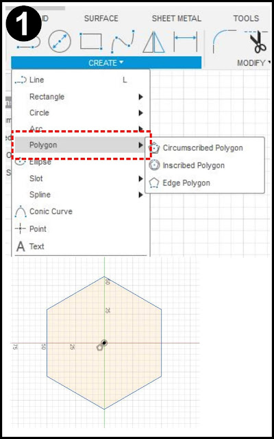
Start a SKETCH and under CREATE, select the POLYGON option. The Circumscribed and Inscribed options work well. Set the number of sides. Click OK when done, then click FINISH SKETCH to exit the sketch mode.

Free printable Fusion 360 tutorial on making faceted gems
Sketch a POLYGON.

(2) EXTRUDE with NEGATIVE TAPERS

Make the TOP: Select the EXTRUDE command. Click on the polygon sketch and pull the extrusion upward to create the top part of the gem. Set the TAPER ANGLE to a negative value. Smaller values will leave a flat top on the gem, higher values will

Sunday, August 18, 2019

Shell Command in Fusion 360

I started keeping some notes about commands in Fusion 360, just some neat tips and tricks I had gleaned from all the how-to videos. These tips were often scattered in videos about other subjects and I had a hard time remembering which part of which videos contained the information I wanted.
Often, I will use the tips in exercises immediately after watching the video to help me remember them better. I started taking some screenshots from the exercises and storing them in a reference file. I would print them out and make notes to help me remember. Eventually I began to type the info directly into the file.

Over time I started to develop a style of note keeping, and I combined these notes with some old illustration files to make it more professional looking (old habits die hard). These screenshots and note files were supposed to be the building blocks for some blog posts and videos, but I started feeling like the illustrations and notes were actually useful just like they were. I still intend to do the videos and tutorial blog posts, but I decided to share these illustrations first.

<a href="https://www.facebook.com/pg/tangoofthegeeks/posts/">FACEBOOK</a>

They are intended to be a very basic framework about the Fusion commands and you are supposed to print them out and scribble your own notes on the sheets in a way that makes sense to you - a kind of DIY cheatsheet for Fusion. They should fit on a US Letter or an A4 piece of paper with a margin for a three hole punch. Collect them all and make your very own custom training manual. Or at least that's my intention.

Making these sheets useful and presentable to the public turned out to be a lot more work than I anticipated. The SHELL command is one of the simplest commands and it still took me several days to make these sheets, to turn all those scribbles into full sentences, put the images into some sort of organized sequence etc. So I'm not sure if this will become a regular feature or not.

If you find this useful, please drop me a note or a comment on the FACEBOOK page so I will know I should produce more.

I divided the notes onto different sheets because I wanted to leave room for people to take notes and make their own drawings. I wound up with several sheets and I'm afraid they became too densely packed with information for much note taking. But this is just a first draft and the format might change in the future - if enough people are interested. Let me know what changes and additions you want - more dense, less dense - more detail, less detail - larger, smaller etc.

THE SHEETS


Each blog page has it's own sheet and some notes. I will come back and add the tutorials to the individual pages, and maybe even a link to a video if I ever make it.

Basics and Introduction

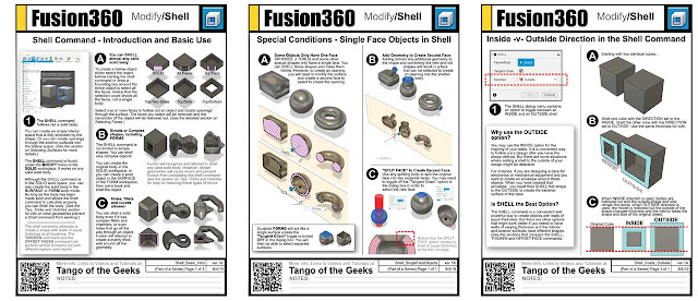
What does the SHELL command do and where do you find it? What kinds of objects can you use it on and are there any complexities to the command? SHELL is a simple command that can save you a lot of time.
Read the Tutorial >>>

Selecting Faces - One, Several or All

- Coming Soon -
Read the Tutorial

Inside or Outside - Setting Shell Direction

The SHELL command lets you choose the direction of the shelling action - INSIDE or OUTSIDE. If you choose INSIDE then it puts the walls along the inside of the existing shape and maintains the existing exterior surface shape. If you choose OUTSIDE then Fusion will add a wall outside of the existing shape and the original geometry will become the hollow interior. This is useful for making casting molds or to maintain clearance when designing cases and enclosures.
Read the Tutorial >>>

Special Conditions - Single Face Objects, Adding Faces

There are a few shapes, a SPHERE or TORUS for example, that only have one face. You can only make these shapes hollow, you cannot punch a hole through them with the Shell command without adding geometry or splitting the face before shelling. FORMS made with the sculpt tools can also act like a single-face object unless you turn off Tangent Chain in the dialog box.
Read the Tutorial >>>

Tips, Tricks and Gotchas

FORMS: Thicken- v- Shell
--- Coming Soon- Shell -v- Extrude Cut - v- Combine Cut
--- Coming Soon- Why Can't I Shell This
--- Coming Soon- Modifying Shelled Bodies
--- Coming Soon- Adding Details - Before or After
--- Coming Soon- Tangent Chain


Videos About The Shell Command

Brad Tallis shows a time-saving way to make a bracket
NYC CNC shows an interesting use to create an odd shape


Check out all of our Fusion 360 Tips, Tricks and Tutorials.


Also find me on:

Shell Inside Outside in Fusion 360

The SHELL command lets you choose the direction of the shelling action - INSIDE or OUTSIDE. If you choose INSIDE then it puts the walls along the inside of the existing shape and maintains the existing exterior surface shape.

If you choose OUTSIDE then Fusion will add a wall outside of the existing shape and the original geometry will become the hollow interior. This is useful for making casting molds or to maintain clearance when designing cases and enclosures.


To understand the difference between the two options, start with

Shelling Single Face Models in Fusion 360

There are a few shapes, a SPHERE or TORUS for example, that only have one face. You can only make these shapes hollow, you cannot punch a hole through them with the Shell command without adding geometry or splitting the face before shelling. FORMS made with the sculpt tools can also act like a single-face object unless you turn off Tangent Chain in the dialog box.


See all sheets on the SHELL COMMAND or take a look at

All of our Fusion 360 Tips, Tricks and Tutorials.


Also find me on:

Shell Command Intro in Fusion 360

What does the SHELL command do and where do you find it? What kinds of objects can you use it on and are there any complexities to the command? SHELL is a simple command that can save you a lot of time.
Fusion 360 Shell command download printable cheatsheet
Download the image and print on A4 or Letter paper for a quick cheatsheet


See all sheets on the SHELL COMMAND or take a look at

All of our Fusion 360 Tips, Tricks and Tutorials.


Also find me on:

Forms Thicken versus Shell in Fusion 360

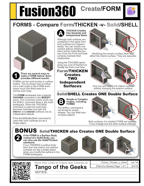
FORMS have special properties in Fusion 360, and there are special commands to work with Forms. Although you can use the Shell command on a Form (while in the SOLID workspace), that might not be your best option.

The FORM workspace's Modify menu has its own THICKEN command. When you use this command you can shell out the form, but both of the resulting surfaces (interior and exterior) act as separate objects in the Modify menu. You can push or pull on one without affecting the other surface (within limits.) This gives you a lot of freedom for sculpting the outside shape and interior cavity.

By contrast, dropping the Form back into the solid workspace and using the SHELL command on the solid form somehow connects the interior and exterior surfaces. When you push/pull on one it also affects the other surface. If that's what you want, this might be very handy.

And if the FORM is an open surface model (not a solid) you can also use the Solid version of the Thicken command (under the create menu.) This option also creates a connection between the two surfaces and causes them to act like a single wall.

Which option is best? Well that depends on what you want to do with the resulting surfaces.

https://tangoofthegeeks.blogspot.com/2019/08/forms-thicken-versus-shell-in-fusion-360.html
Download and print on A4 or Letter for a custom Fusion 360 manual cheatsheet.


See all sheets on the SHELL COMMAND or take a look at

All of our Fusion 360 Tips, Tricks and Tutorials.


Also find me on:

Thursday, December 20, 2018

Mimic Springs or Gravity in Fusion 360

Use the REST option in combination with JOINTS and CONTACT SETS to mimic the effect of gravity or a spring-return action in your Fusion 360 designs. Now your cam-followers will actually follow the cam surface for the entire rotation, latches can snap back into position, and you can more accurately model the actions of your mechanisms.

WHY?
Sure, even without utilizing the REST option you can use contact sets and make one object push another object out of the way. But the moved object stays in the new location. It does not return to its original position. If a cam pushes a rod up, the rod stays up and never returns to its lower position. A latch pin can be pushed out of the slot, but it will not automatically slide into the locked position

But when the REST option is used, the object does return to its original position. The REST option basically tells Fusion to always return that object to its original resting position. The REST option works with all joint types, so you can create a self-centering joystick, a slide that returns to bottom, a spring-loaded pin or a combination.

I've always used this technique in combination with contact sets, but it does work with basic joints too. I use the contact sets to create the interaction between the objects, then create a resting position to make sure the moved object returns to the desired position when the contact set's influence ends. However, you can create a joint without contact sets, a simple pendulum for example, and the object will return to resting position when you release the mouse after moving it. (Note: This changes the way the "Capture Position" option works.)

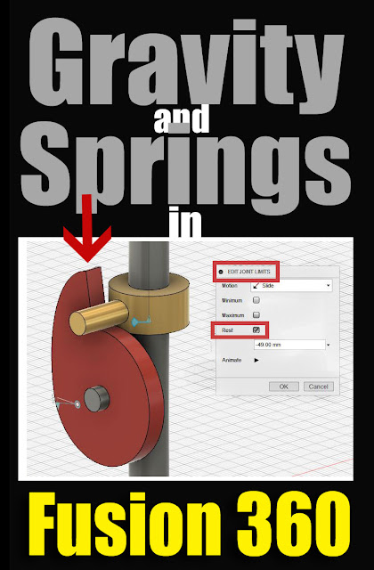
gravity and springs in fusion 360 joints and contact sets
Use the "REST" option in the "Edit Joint Limits" menu along with contact sets to apply, or at least mimic, the effect of gravity or springs in Fusion 360 models and animations.


SETTING the REST POSITION:
  • Open the JOINTS folder in the object browser
  • Find the Joint you want to have a Resting Position
  • Start the "Edit Joint Limits" dialog by:
    a) Right-clicking and selecting from the menu
    b) or hover over the joint and select the icon to the right of the joint name.
  • Select the REST check box
  • When selected, an option to enter the location of the REST or "home" position appears
  • The type of value changes depending on the joint type (ex: sliders use a distance, rotating joints (revolutes) use degrees
  • I try to design the model so that the object's original or current position is the resting position. But you can enter any functional positive or negative value.
  • Notice that you can drag the object using the triangle-flag icon that appears
  • Click OK


Now, the "Rested" component will try to return to the home-position whenever the contact surface stops pushing it out of the way. The affect happens quickly, much like having a spring applied to it.

The REST option is an excellent way to model assembly joints, but it does have limits.
  • Objects do not bounce.
  • There is no decay, so pendulums return instantly to center instead of swinging in smaller arcs
  • There is no acceleration/deceleration.
  • There is no friction or speed options that I know of.
  • It does not deform modeled springs or levers.

So it's definitely not a full kinematics modeler and the interaction is very simple. But overall it's a very useful technique that is worth remembering.

Check out all of our Fusion 360 Tips, Tricks and Tutorials


As an Amazon Associate I earn from qualifying purchases.
Shop through our Amazon links to help support this site.

Also find me on:

Saturday, May 19, 2018

Trim Command - Fusion360 Quick Tip

Even with Fusion 360's great sketch tools, sometimes your sketch can become cluttered. That's not a big problem on simpler sketches. But in a complex sketch all those extra lines crisscrossing everywhere can become confusing.

The TRIM command lets you get rid of all those extra lines and clean up your sketches so that they're easy to work with.
  • Under the SKETCH menu, select the TRIM command. Or type "T" to invoke the command.
  • If you are not already in a sketch, you will be prompted to select a sketch to work with.
  • The cursor will change to a "scissors" icon.
  • You can select either a single line or "paint" across multiple lines to delete all of them at once

Fusion 360 Trim command


Single Lines: When you move the cursor over a line, the selected line segment will turn red to indicate which portion of the line will be deleted. When you left-click on the highlighted segment, that segment will be deleted (trimmed).

Painting Multiple Lines: You can also left-click and hold the mouse button down as you move the cursor across multiple lines. All line segments that your cursors crosses while the mouse button is down will be deleted.

Since Fusion stops trimming at the first boundary, you must continue clicking line segments to delete across multiple boundaries.
  • Construction lines can also function as trimming boundaries.
  • Although I call them lines, TRIM also works on curves, splines and shapes (e.g. circles, rectangles).
  • However, lines and boundaries must be on the same plane (share a point in space). For instance, you cannot use a 3d spline as a trim-boundary if does not intersect the line to be trimmed.


Notice that Fusion 360 makes intelligent guesses about which line segments you want to delete (trim). Fusion will select segments based on crossing boundary lines and end point nodes. Fusion will trim the line to the nearest crossing or node. If there are crossings or nodes on both ends, Fusion will trim out the center section.

Fusion 360 Trim command
The selected segment will turn red when you roll the cursor over it. Left-click on the highlighted segment to delete (trim) it. If there is only one boundary, Fusion will delete the line up until that boundary.


Fusion 360 Trim command
When there are two boundaries, Fusion will trim the segment that lies between the two boundaries.


My preferred method is to draw all my lines into the sketch. After I've drawn all my basic geometry I then go back and start trimming lines to clean up the sketch. I find that this sequence avoids the problems that happen when Fusion creates relationships and constraints between the lines.

However, these relationships and constraints are also very useful. For instance, Fusion will adjust the gap created if you trim a segment, then move the boundary line.

The TRIM command's opposite is the EXTEND command.

The BREAK command divides  a line into segments at a boundary, but does not delete any part of the line.


As an Amazon Associate I earn from qualifying purchases.
Shop through our Amazon links to help support this site.

Also find me on: